
Portable Mesh Node
Bill of Materials
Here is the bill of materials for the portable node. Please note that this is intended more for RACES/ACS emergency use, but can be used for the public service events.
- Weewooday 12V to 5V DC Converter
- XtremPro 5 Port USB Powered Hub
- Tycon Systems 12V to 24V DC Converter POE
- USB Mail to 2 Dual Usb Female Jack Y Splitter
- HiLetgo USB Male to DC 5.5x2.1mm 5 volt DC Connector
- Ethernet Wall Plate
- Plastic Carrying Case
- GearIT 10 Pack, Cat 6 Ethernet cable
- Linkstyle 4 in 1 Marine Switch Panel
- Powerwerx Chassis Mount Kit
- Powerwerx Power Distribution
Here are some quick notes and thoughts about the build:
The box itself supports any of the mesh nodes over the POE port. In my case, I use Ubiquity NSM5.
The carrying cases I chose are pretty tight for the configuration, but that was my original goal. They came with padding glued to the cover that was a royal PITA to remove. Cutting all the holes was a bit of a challenge and the latching mechanism feels pretty rickety. I expect them to break as I continue to open and close the boxes to demonstrate their interior. I will probably build a 3rd box that is a bit bigger, but will provide more utility. That box I'll just use the Powerwerx Battery Box. It will be a bit more expensive, but offers more room, and I will put a battery inside the case as well, instead of using an external battery.
As stated above, these boxes were initially intended for emergency usage, and I included two Grandstream GXP1620 IP Phone and a Raspberry Pi running Asterisk PBX controller to run the network. Each box is capable of running 5 phones in the current configuration. My theory is that in an emergency, it might be easier to provide our served agencies with a familiar communications tool - the telephone - for voice communications, instead of attempting to channel all communications through a microphone. This way, one licensed operator can provide effective communications for a whole group of people.
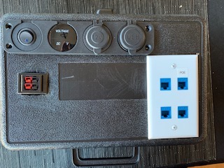
External View
I chose to put the marine switch panel in the upper left corner of the box. The two covered access ports are for 2 USB charging ports and an automotive connector. On the first build, I left those two components unswitched. For the second build, I decided to control everything with the switch.
The USB charging ports can be used for a number of things, from a USB light, to powering other 5V devices. I use the USB to barrel connector to power the phones for the demo package. The automotive adaptor is unused at this point, but it could also be used for input power.
Beneath that is a Powerpole panel connector. Initially I planned to put a battery in the case and use that for output power. But once I started putting components in, I decided to make that input power. I only used the top connector at this point as a result.
The 4 port Ethernet panel contains one POE and 3 regular RJ45 connectors. I labeled the POE port to prevent inadvertently connecting non-POE equipment and potentially seeing a smoke test produce real smoke!
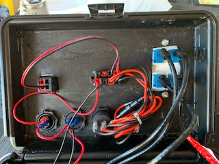
Top View
I chose to use a Powerwerx power junction and Powerpoles to minimize the amount of soldering I needed to do. It also allowed me to move things around. The junction adaptor is hot glued to the surface.
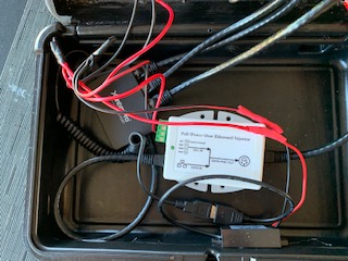
Bottom View
The POE connector goes to the POE output side of the Tycon Systems power converter. The other three ports, and the input to the Tycon are connected to the USB powered Ethernet hub. On the front wall (lower edge in the picture), I hot glued the 12V to 5V converter and connected the 5V output to the Ethernet Hub for power. In the second box, I used a USB Male to 2 Female adaptor to also power the Raspberry Pi.
I originally thought about hot gluing those components, but decided to switch to velcro so I can remove things if I need to. I also found that opening and closing the box is putting a lot of stress on the CAT 6 cables, so leaving things loose may be my ultimate solution.
- Log in to post comments